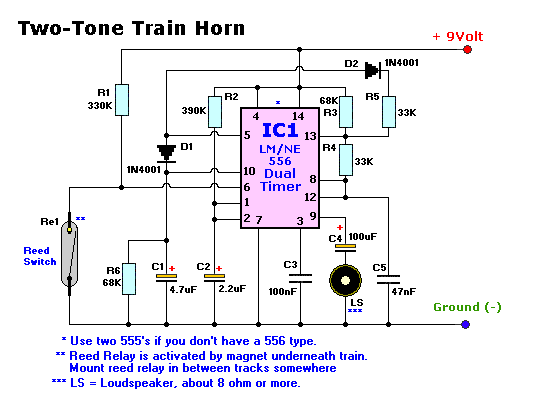
Parts List
R1 = 330K                        C1 = 4.7 uF/16volt
R2 = 390K                        C2 = 2.2uF/16volt
R3 = 68K                         C3 = 100nF, ceramic
R4 = 33K                         C4 = 100uF/16volt
R5 = 33K                         C5 = 47nF, ceramic
R6 = 68K                         LS = 8 Ohm, 0.25 - 2watt.  Others may work too.
S1 = on/off switch
Re = Reed Relay (glass tube)
IC1 = NE556 (or use two 555's)
D1 = 1N4001
D2 = 1N4001
Final Notes:
Circuit is build up arround the LM
or NE556 dual timer. Each timer producing a high or a low tone. The 556
contains two seperate 555 timers so feel free to use the 555's. If you don't
want to fiddle with the reed relay that is fine too. Just put a push on-off
switch between negative and pin 6 of IC1. If you go with the reed relay, mount a
strong magnet underneath the locomotive and mount the reed relay somewhere
between the tracks on a place where you want the horn to be sound. Make sure the
reed relay is positioned in such a way that the magnet is able to close the
contacts. The sound is very realistic. Have fun!
Back to Gadgets
Menu page
Copyright © Tony van Roon

